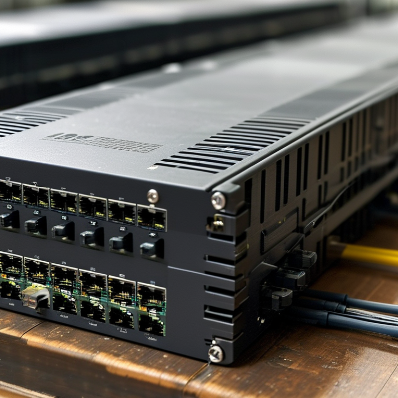
Choosing the best Module Transceiver for global buyers requires more than comparing data rates. A reliable decision connects performance, compatibility, supply stability, and long-term operating cost. Buyers must examine fiber type, wavelength, reach, connector design, power consumption, and diagnostic support. Small details matter. A label can prevent a costly installation mistake.
Professor David A. B. Miller, a leading authority on optical communication, has emphasized, “The key issue is energy per bit, not simply bandwidth.” This principle remains practical for modern data centers, telecom networks, and industrial links. A 400G module may look impressive, yet it can create thermal problems in a crowded switch. A lower-power 100G option may deliver better value for regional infrastructure. Context decides.
This guide evaluates the 2026 Module Transceiver market through an evidence-based lens. It considers laboratory specifications, field experience, vendor documentation, and buyer feedback. Global purchasers also need dependable quality control and clear warranty terms. Availability can change quickly. So can compliance requirements, exchange rates, and shipping conditions.
No ranking is perfect. That deserves attention. Some products perform well in controlled tests but struggle with dust, heat, or mixed-vendor environments. Others offer excellent value but provide limited monitoring tools. Readers should verify current datasheets and request compatibility testing before placing large orders. The strongest choice is not always the fastest module. It is the one that remains stable, supportable, and economically sensible after installation.
Module transceivers are compact communication devices that send and receive data through fiber or copper links. They connect switches, routers, servers, and other network equipment. In practical deployments, the module must match the port, transmission distance, data rate, and operating temperature. A mismatch can cause unstable links, packet loss, or complete communication failure.
A transceiver performs two main functions. Its transmitter converts electrical signals into optical signals, while its receiver converts incoming light back into electrical data. Core components usually include a laser or light-emitting source, photodiode, driver circuit, receiver amplifier, and digital monitoring unit. The housing protects these parts from dust and vibration. Electrical contacts provide host-side communication, often through a small pluggable interface. Firmware can report temperature, voltage, and optical power.
During equipment checks, I inspect connector cleanliness before testing signal quality. A few particles can weaken an otherwise healthy link. Buyers should also verify wavelength, fiber type, polarity, and maximum reach. Technical documents often look complete, but compatibility details may remain unclear. That deserves careful questioning. Power consumption matters in dense racks, where heat builds quickly. Coding support and diagnostic accuracy also affect maintenance speed. I have seen modules pass a short laboratory test yet perform poorly in crowded cabinets. Long-term reliability needs repeated temperature, traffic, and insertion testing. Availability is important, but predictable performance matters more.
Choosing a module transceiver starts with the network, not the product label. Confirm the required data rate, transmission distance, wavelength, and fiber type. A short indoor link may need a different optical design than a 40-kilometer connection between regional facilities. Check connector format and housing compatibility before ordering. A small mismatch can delay installation.
Power consumption deserves close attention. Lower power can reduce heat inside dense racks, especially where airflow is limited. Review the operating temperature range for outdoor cabinets, factory floors, and uncontrolled server rooms. Digital monitoring can report temperature, voltage, and optical levels. This information supports preventive maintenance, although readings should be compared with field measurements. Monitoring alone is not proof of link health.
Interoperability is equally important for global buyers. Verify host equipment support, coding requirements, fiber loss limits, and software recognition. Confirm applicable safety, electromagnetic, and environmental documentation for each target market. Independent test records are more useful than broad performance claims. I have seen projects choose a higher-speed module before checking switch compatibility. That decision created unnecessary replacements. Higher speed is not always better. Allow room for uncertainty. Supply continuity, firmware behavior, and replacement availability may change during a multi-year deployment. A practical evaluation should include sample testing under real temperature, distance, and traffic conditions.
For global buyers in 2026, transceiver selection should begin with distance, environment, and required speed. Fiber transceivers suit long links, electrical isolation, and high electromagnetic interference. Single-mode fiber can cross campuses or metropolitan sites, while multimode fiber fits shorter data-center paths. Copper transceivers remain practical inside racks. They usually cost less and simplify installation, but heat and cable length can limit performance. Wireless transceivers help remote or temporary connections, especially where cabling is difficult. However, obstacles, interference, weather, and local radio rules require careful validation.
High-speed transceivers support demanding workloads, including cloud traffic, storage systems, and real-time analytics. A 100G or 400G link may look attractive, yet the switch, fiber plant, connectors, and cooling system must support it. During deployment reviews, I check insertion loss, port compatibility, temperature range, and diagnostic reporting. A clean specification sheet is not enough. I have seen a fast module fail because an older cable assembly was overlooked.
Tips: Measure the actual link distance. Confirm connector types and transmission standards. Test wireless paths at busy hours, not only at night. For copper, check rack temperature and cable routing. For high-speed links, leave capacity for future upgrades, but avoid paying for unused bandwidth. Independent testing adds confidence, especially when shipments cross climates and installation teams change. Even experienced buyers can miss one detail. Recheck the whole path.
| Transceiver Type | Transmission Medium | Typical Data Rates | Typical Reach | Typical Latency | Typical Power Range | Common Interface or Connector | Common Standards or Technologies | Best-Fit Applications | Main Advantages | Key Limitations | Global-Buyer Selection Priority |
|---|---|---|---|---|---|---|---|---|---|---|---|
| Multimode Fiber Module | Multimode optical fiber, usually 50/125 µm | 1, 10, 25, 40, and 100 Gb/s are common deployment classes | Approximately 70–550 m, depending on speed, fiber grade, and optical budget | Typically below 1 µs module contribution; system latency varies | Approximately 0.7–4.5 W | SFP, SFP28, QSFP+, or QSFP28; duplex LC or multi-fiber MPO/MTP-style connector | Ethernet, Fibre Channel, parallel and duplex short-reach optical links | Data-center server access, rack-to-rack links, enterprise aggregation | High bandwidth, electrical isolation, low electromagnetic interference, efficient for short distances | Shorter reach than single-mode fiber; requires compatible multimode cabling and optical cleaning | Match fiber grade, polarity, connector type, optical budget, and host compatibility |
| Single-Mode Fiber Module | Single-mode optical fiber, typically 9/125 µm | 1, 10, 25, 100, 200, and 400 Gb/s; higher rates are available in specialized systems | Approximately 2–80 km for common Ethernet modules; extended systems can reach farther | Usually about 5 µs per km of fiber, plus equipment processing delay | Approximately 1–8 W, depending on rate and optical reach | SFP, SFP28, QSFP28, QSFP56, or QSFP-DD; LC, duplex LC, or MPO/MTP-style connector | Ethernet, CWDM, DWDM, coherent and long-reach optical transport | Campus networks, data-center interconnects, telecom access, metropolitan links | Long reach, strong EMI immunity, high scalability, and low weight per kilometer | Higher optics and installation cost; sensitive to connector contamination and bend loss | Verify wavelength, optical budget, dispersion limits, fiber route, and regional import requirements |
| Direct-Attach Copper Cable | Twinaxial copper cable with integrated transceiver ends | 10, 25, 40, 100, and 400 Gb/s versions are used in short-reach systems | Commonly 1–5 m for passive versions; active versions may reach approximately 7–10 m | Very low; generally lower than an equivalent optical link of the same length | Approximately 0.1–1.5 W per end, excluding host-system power | SFP+, SFP28, QSFP+, QSFP28, QSFP56, or QSFP-DD ends | Ethernet and other high-speed serial interconnects | Top-of-rack connections, server clusters, storage networks, and in-rack links | Low cost, low power, simple installation, and excellent short-distance latency | Heavy and less flexible than fiber; limited reach and greater sensitivity to electromagnetic conditions | Confirm cable length, bend radius, port coding, lane configuration, and airflow impact |
| Twisted-Pair Copper Module | Shielded or unshielded balanced copper Ethernet cabling | 1, 2.5, 5, and 10 Gb/s are common; some specialized systems support higher rates | Up to 100 m for standards-compliant structured cabling, depending on category and rate | Usually low, but higher than a short DAC link because of signal processing and cable length | Approximately 1.5–4 W, with higher consumption possible for multi-gigabit modules | SFP or SFP+ module with an 8P8C modular jack | Ethernet over Category 5e, Category 6, or Category 6A cabling | Existing office cabling, access switches, industrial Ethernet, and short building links | Uses installed copper infrastructure and supports familiar field termination practices | Higher power and heat than optical alternatives; affected by EMI, grounding, and cable quality | Check cable category, maximum channel length, thermal design, auto-negotiation, and PoE compatibility |
| Wireless Transceiver Module | Radio frequency transmission through air, often with an external or integrated antenna | From hundreds of Mb/s to multi-gigabit rates, depending on radio technology, channel width, and conditions | Indoor range commonly 10–50 m; outdoor point-to-point links may span kilometers with suitable antennas and regulation | Typically milliseconds for contention-based links; specialized systems can be lower | Approximately 0.5–10 W, excluding high-power outdoor radio equipment | M.2, mini-PCIe, board-to-board, or embedded radio interface; antenna connectors vary | Wi-Fi, private cellular, industrial wireless, microwave, or millimeter-wave radio | Mobile equipment, temporary links, smart factories, remote sites, and difficult-to-cable locations | Fast deployment, mobility, flexible topology, and reduced physical cabling | Shared spectrum, interference, weather sensitivity, security requirements, and variable throughput | Confirm permitted frequency bands, regional certification, antenna gain, encryption, and line-of-sight needs |
| 100G High-Speed Optical Module | Single-mode or multimode optical fiber, depending on the module variant | 100 Gb/s aggregate throughput, commonly using four 25 Gb/s lanes or parallel optical lanes | Approximately 70 m to 10 km for common data-center and campus variants | Usually below 1 µs module contribution; fiber distance adds propagation delay | Approximately 2.5–6 W | QSFP28; LC duplex or MPO/MTP-style connector | 100GbE, four-lane electrical host interfaces, and parallel or duplex optical transmission | Leaf-spine data centers, high-performance computing, and enterprise aggregation | Mature ecosystem, broad interoperability, high port density, and manageable power consumption | Requires precise lane mapping, fiber polarity, and host-port compatibility | Validate breakout support, FEC requirements, connector polarity, and operating temperature |
| 200G High-Speed Optical Module | Primarily single-mode optical fiber; short-reach variants may use parallel multimode fiber | 200 Gb/s aggregate throughput, commonly based on four 50 Gb/s lanes | Approximately 100 m to 2 km for common deployment options | Typically below 1 µs module contribution | Approximately 4–8 W | QSFP56; duplex LC or MPO/MTP-style connector | 200GbE, PAM4 signaling, forward error correction, and four-lane architectures | Data-center spine links, high-density aggregation, and scalable server fabrics | Higher capacity without immediately moving to larger eight-lane modules | More sensitive to insertion loss, host signal quality, thermal limits, and FEC configuration | Check electrical lane rate, breakout topology, optical loss budget, and switch firmware support |
| 400G High-Speed Optical Module | Single-mode optical fiber for most data-center and interconnect deployments | 400 Gb/s aggregate throughput, commonly using eight 50 Gb/s lanes or four 100 Gb/s lanes | Approximately 100 m to 10 km, depending on optical architecture | Typically below 1 µs module contribution; link distance adds propagation delay | Approximately 8–15 W | QSFP-DD or OSFP; duplex LC or MPO/MTP-style connector | 400GbE, PAM4, FEC, parallel optics, and breakout to lower-rate interfaces | Large-scale cloud data centers, artificial-intelligence clusters, and data-center interconnects | Very high throughput, improved port density, and efficient scaling of spine networks | Higher heat, stricter host compatibility, and greater cabling and installation complexity | Prioritize cage type, thermal headroom, FEC mode, breakout support, and power-delivery capacity |
| 800G High-Speed Optical Module | Primarily single-mode optical fiber for data-center and AI-cluster fabrics | 800 Gb/s aggregate throughput, commonly implemented with eight 100 Gb/s electrical or optical lanes | Approximately 100 m to 2 km for common high-density deployments | Typically below 1 µs module contribution; total latency depends on the complete link | Approximately 12–18 W, with some implementations requiring more thermal capacity | OSFP or QSFP-DD800; duplex LC or multi-fiber MPO/MTP-style connector | 800GbE, 100G-per-lane PAM4, FEC, and high-density breakout architectures | AI training clusters, hyperscale data centers, and next-generation spine networks | Maximum port capacity, fewer physical links for equivalent bandwidth, and strong upgrade potential | High power and heat density; interoperability, firmware, cabling, and service expertise are critical | Confirm switch support, cage airflow, thermal limits, lane mapping, FEC, and regional service capability |

2026 Best Module Transceiver for Global Buyers
Global compatibility starts with radio bands, not marketing claims. A module must match local spectrum plans, operator certification, antenna design, and power limits. LTE Cat 1 bis, LTE-M, NB-IoT, and 5G options serve different deployment needs. The correct choice depends on mobility, coverage, latency, and battery life.
GSMA Intelligence projects 34.4 billion cellular IoT connections by 2030, up from 18.8 billion in 2024. That growth increases pressure on suppliers to support regional band combinations. Ericsson’s November 2024 Mobility Report forecasts 2.3 billion 5G subscriptions by the end of 2024. Yet 4G remains essential in many rural and industrial areas. A practical transceiver should support relevant 3GPP releases and offer fallback paths where networks are uneven.
Regional validation requires more than a laboratory checklist. European deployments may require CE compliance and bands such as 800, 900, and 1800 MHz. North American projects often need FCC approval, PTCRB testing, and different LTE band combinations. Asia-Pacific markets vary sharply, even between neighboring countries. Confirm GCF or equivalent certification before volume orders. I have seen projects fail after a technically strong module met the wrong band plan. Spreadsheets can mislead. Test roaming, carrier attachment, thermal behavior, and antenna performance with local SIMs. A smaller module is not always the better global choice.
Representative 3GPP LTE band-count checklist for regional deployment planning. The figures show commonly deployed LTE bands that a globally compatible cellular module may need to support; actual operator requirements vary by country and network.
Global buyers should verify LTE FDD/TDD support, 3GPP compliance, regional certification, carrier approval, and local frequency allocations before selecting a transceiver module.
Choosing the best module transceiver in 2026 requires more than comparing data rates. Performance should match the network’s real operating conditions. Check throughput, latency, optical reach, power consumption, and error performance under continuous load. A module that passes a short test may still overheat inside a crowded cabinet. Test it at minimum, normal, and maximum temperatures.
Reliability depends on stable firmware, accurate diagnostics, and consistent manufacturing. Request temperature ratings, failure-rate data, compatibility records, and traceable test reports. Watch the details. A useful diagnostic interface can reveal rising temperature before service disruption occurs. However, published figures are not always enough. Independent validation with your own switches and fiber can expose compatibility gaps. This step takes time, but replacing modules across remote sites costs much more.
Cost should include installation, energy use, support, returns, and future availability. The cheapest quotation may become expensive after repeated troubleshooting. Supplier support matters during those uncomfortable moments. Look for clear documentation, responsive technical staff, spare-stock planning, and realistic warranty terms. Regional delivery capability can reduce delays for global projects. A supplier should explain limitations, not only advertise strengths. I would still leave room for doubt: product samples may not represent every production batch. Small pilot orders, written test criteria, and scheduled reviews create stronger purchasing decisions.
© 2025 Grandmark International. All rights reserved.
© 2020 Grandmark. Grandmark International. All rights reserved. Proud shareholder of Temot International.